Route 23A, Jewett County, New York
| Route 23A, Jewett County, New York |
|
|
|
|
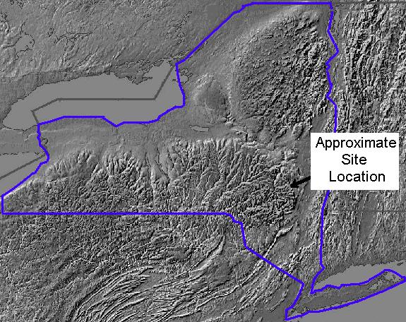
In May of 1995, NYSDOT initiated an embankment stabilization project incorporating EPS geofoam blocks along a section of NYS Route 23A between Jewett and the Town of Hunter in Greene County. |
|
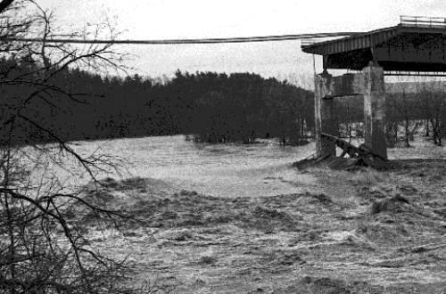
The reconstructed section of NYS Route 23A runs parallel to Schoharie Creek, a fast-rising, Class 1 trout stream within the New York City water supply. The photo below shows the damage caused by Schoharie Creek to the I-90 crossing following a severe storm flood. |
|
|
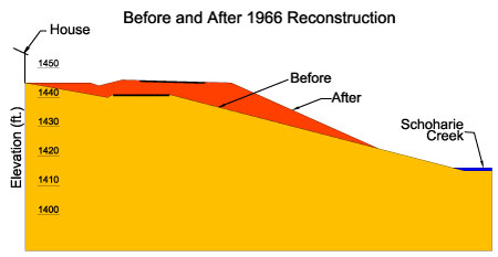
In 1966, the New York State Department of Public Works reconstructed the stretch of Route 23A. The centerline of a gully crossing was shifted about 10 ft towards the creek and raised approximately 5 ft in elevation. The re-alignment provided increased shoulder width, improved line-of-site, and increased safe travel speed. A before and after 1966 cross-section is shown below. |
|
|
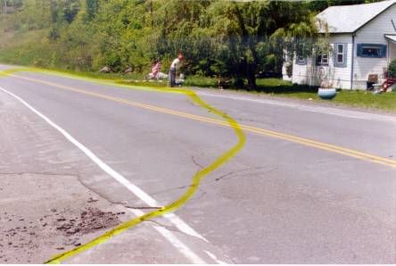
Shortly after construction, a 300-ft long section of the roadway embankment began a slow-moving slide towards the creek. Frequent pavement patching was required to seal pavement surface cracks that developed along the area of sliding as shown outlined in the photograph. |
|
|
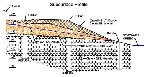
In 1978, NYSDOT conducted a subsurface exploration program consisting of cased borings with continuous sampling to determine the soil stratigraphy and observe groundwater levels over time. The borings extended up to 63 ft below surface and groundwater levels were noted to vary between 5 to 15 ft below surface. The subsurface stratigraphy consisted of "Gravelly SILT, Clayey" (recent fill material), over "Layered Clay SILT, Silty CLAY" (older fill material), overlying "Clayey SILT, Gravelly". |
|
|
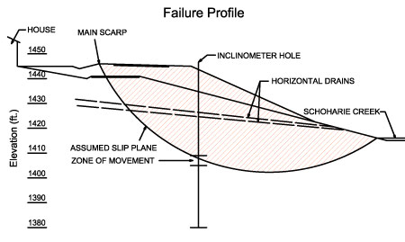
In 1979, a fan-shaped series of 22 horizontal drains was installed along the toe of the slope in an attempt to reduce groundwater pressures and stabilize the embankment. An inclinometer was also installed near the center of the failure area to help identify the zone of sliding (see figure below) and monitor the rate of movement. Inclinometer data collected over the next 14 years indicated an annual rate of movement of less than 1 inch per year and a total movement towards the creek of about 8 in. Movement was noted to occur mainly in a zone of 36 to 40 ft below ground surface and at an elevation of approximately 10 to 15 feet below Schoharie Creek. |
 |
|
The lateral drain system was not effective in arresting the slope movement and was considered unsuccessful. The slope movement had to be stopped without changing the roadway grade and alignment. In 1994, the following stabilization alternatives were considered by NYSDOT: |
|
|
|
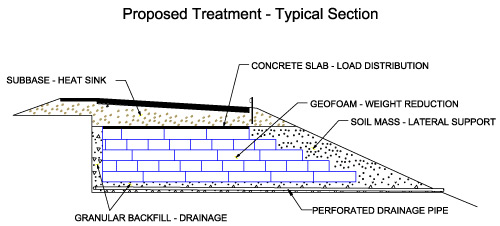
The option of slope stabilization by replacing soil with geofoam within the upper portion of the embankment was selected. Excavation and replacement of soil mass with geofoam was realized to result in an order-of-magnitude decrease in gravitational driving forces. Construction could occur any time of the year and would be relatively easy and fast. |
|
|
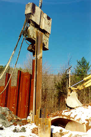
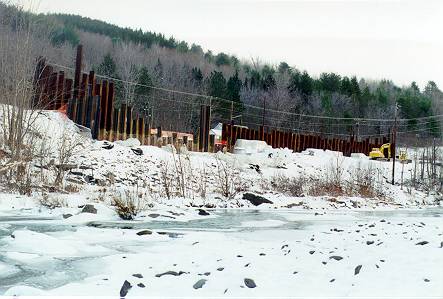
Construction began with installation of a new inclinometer in the middle of the failure area. The inclinometer that had been installed in 1979 was sheared. Steel sheet piling was installed along the existing roadway using a vibrating sheet-pile driver. Traffic lights were installed and one-lane of traffic was maintained during construction. Ground surface velocities were monitored during construction to ensure that vibrations near the adjacent house did not exceed a 50mm/sec (2 in/sec) threshold. The inclinometer measured a total of about 25mm (1 in.) of lateral movement between 6.1 and 9.2m below ground surface, following installation of the sheet piling. |
|
|
|
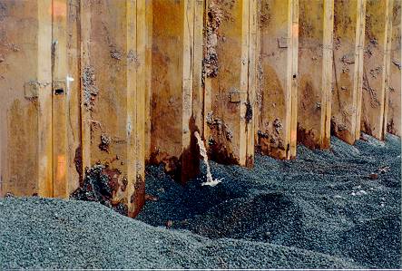
Excavation of the existing embankment then proceeded along the downslope side of the sheet pile wall to a depth of approximately 4.7 m (15 ft). During excavation, the top of the sheet pile wall moved about 0.6m (2 ft) towards the creek and groundwater was visible in the opening where the sheet pile wall separated from the soil on the upslope side. Holes were drilled through the sheet piling near the bottom of the excavation to relieve the water pressure behind the sheet pile wall. |
|
|
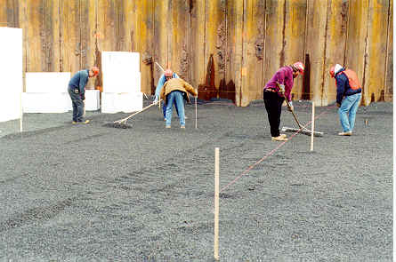
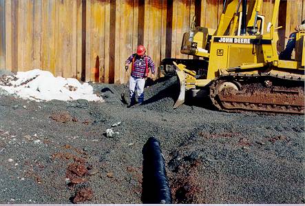
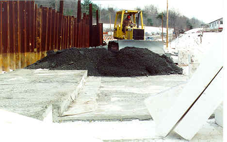
At the required excavation depth, 0.6 m (2 ft) crushed stone was placed on the subgrade and roughly graded to design elevation using a bulldozer. The crushed stone extended from the face of the sheet pile wall to the downslope face of the embankment. A 150 mm (6 in) perforated drainage pipe was installed within the crushed stone, transversely from the sheet pile wall to the face of the embankment. Piezometers were installed within the drainage blanket to monitor post-construction groundwater pressures. The crushed stone surface was fine-graded to a specified tolerance of +/- 0.5 percent using hand rakes. |
|
|
|
EPS geofoam blocks arrived at the site on flatbed trailers. On average, it took about one hour for six workers to unload and place one trailer load of blocks (73 m3 or 95 yd3). |
|
|
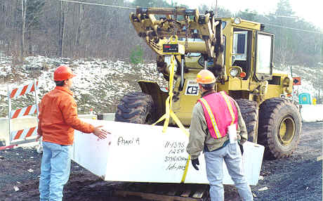
The dimensions of one randomly selected block per trailer were measured for quality assurance. The block was weighed using a field scale suspended from a loader. The block density was determined and compared to the specified value. |
|
|
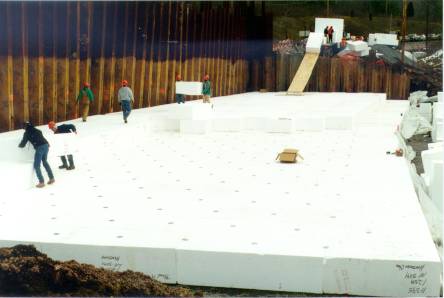
Workers were allowed to walk directly on the unprotected, 20 kg/m3 (1.25 lb/ft3) EPS geofoam blocks. Blocks were installed in layers with each layer orientated at 90 degrees from the underlying layer to promote interlock. Two galvanized steel binder plates per block were used to secure the blocks into position during construction. Lateral extensometers were installed between geofoam layers in the direction perpendicular to the roadway to monitor movement along geofoam block interfaces. |
|
A "hot-wire" cutter was used to field cut some blocks. Field cutting was done to accommodate curvature of the alignment and to achieve the designed geometrical configuration of the EPS geofoam fill. |
|
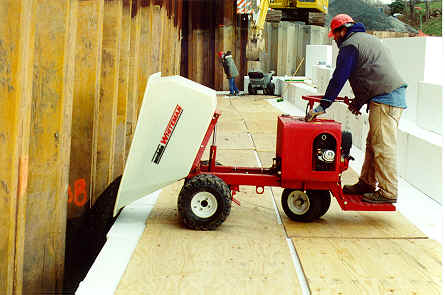
As additional EPS geofoam layers were placed, crushed stone drainage material was placed between the geofoam fill and the sheet pile wall. The crushed stone behind the geofoam fill was to intercept and lower the groundwater by discharging through the crushed stone drainage blanket and drain pipe below the geofoam fill. Plywood was used to protect the EPS geofoam surface from construction loads such as the small, motorized wheelbarrow used to place the crushed stone. |
|
|
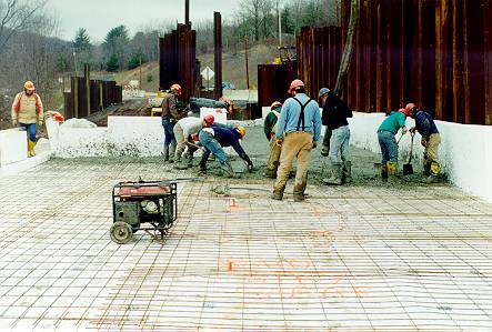
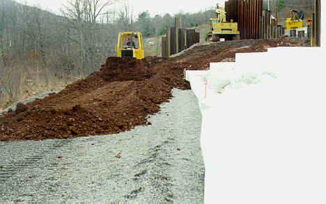
EPS geofoam was cut from full-size blocks and used as forming for 100 mm (4 in) concrete slab. Binder plates were used to secure the side forms. Wire mesh was placed and workers rough screeded the concrete as a final finish. The geofoam forms were then removed and reused elsewhere. Insulating blankets were placed over the slab while curing in cold weather. The side slope of the geofoam fill was backfilled with soil cover up to the level of the slab as the concrete was curing. |
|
|
Between two to four feet of graded crushed stone subbase was placed above the concrete slab. Thermistors were installed within the subbase at locations in and outside of the EPS geofoam fill area to determine differential temperatures. The sheet piling was removed using a vibratory hammer and additional crushed stone drainage material was placed into the void between the EPS geofoam fill and the retained slope. An additional lateral movement towards the creek of about 50mm (2 in) was recorded by the inclinometer during sheet pile extraction. |
|
|
|
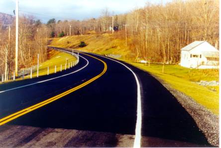
Construction of a 225 mm (9 in) thick asphalt pavement and installation of guardrails completed the project in 1996. Approximately 2800 m3 (3700 yd3) of geofoam was used for the Rt. 23A slope stabilization project, resulting in a net reduction in driving mass of approximately 5400 metric tons (5900 tons), or about 58 metric tons (64 tons) per meter length. |
|
|
|
|
References |
|
GRC report on; Slope Stabilization with Geofoam, demonstration research project jointly funded by the NY Section of the Federal Highway Administration (FHWA) and the Foamed Polystyrene Alliance (FPA). |
|
Jutkofsky, W.S., (1998). "Geofoam Stabilization of An Embankment Slope - A Case Study of Route 23A in the Town of Jewett, Greene County." New York State Department of Transportation. Geotechnical Engineering Bureau. November, 1998. |
|
Jutkofsky, W.S., Sung, J., Negussey, D., (2000). "Stabilization of an Embankment Slope with Geofoam." Presented at the Transportation Research Board, 79th Annual Meeting, January 9-13, 2000, Washington, D.C. |
|
Sheeley, M., (2000). "Slope Stabilization Utilizing Geofoam", M.S. Thesis, Syracuse University, Syracuse, N.Y. |