Slope Stabilization
| Slope Stabilization |
|
|
|
| Geotechnical engineers have long recognized the utility of lightweight fill to reduce mass and associated gravitational driving forces. Lightweight materials that have been used in embankment construction include chipped bark, sawdust, dried peat, fly ash, slag, cinders, cellular concrete, lightweight aggregates, expanded polystyrene, shredded tires, and sea shells (Holtz and Schuster, 1996). |
|
EPS geofoam is up to 50 times less massive than other lightweight fills (see table). To achieve a net reduction in driving mass of 100,000 kg within an embankment having an in-place soil density of 2100 kg/m3 would require placing about 90 m3 of lightweight fill of 1000 kg/m3 density or about 50 m3 of EPS geofoam. |
|
|
|
Material |
Density for calculation (kg/m3) |
|
Bark1 |
1000-1100 |
|
Sawdust1 |
1000 |
|
Cellular concrete waste1 |
1000 |
|
Light expanded clay (Leca)1 |
800-1000 |
|
Waste bricks of Leca1 |
1000 |
|
Tires2 |
700-950 (in-place) |
|
Pumice3 |
1225 |
|
Expanded polystyrene geofoam4 |
15-120 |
|
1 Rygg, N., Sorlie, A., (1981). "Plastic Foam in Road Embankments." Soil Mechanics Conference, Stockholm. |
|
2 Humphrey, D.N., Dunn, P.A., and Merfeld, P.S. (2000). "Tire Shreds Save Money for Maine." TR News, No. 206, January-February, 2000. |
|
3 Holtz, R.D. and Schuster, R.L., (1996). Stabilization of Soil Slopes. In: Landslides Investigation and Mitigation. Transportation Research Board Special Report 247. National Academy Press, Washington, D.C., p. 429-473. |
|
4 Dependent on drainage conditions and nominal geofoam density. |
|
Advantages to using geofoam for slope stabilization may include: |
|
Maximizing available right-of-way |
|
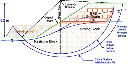
To improve a slope safety factor against failure, different approaches may be considered. A conceptual scheme of slope stabilization with geofoam is shown below. The balance of driving and resisting segments within a potential failure mass may require adjustment. A potential sliding block can be divided into an upper and a lower masses. The upper mass, contributing more to driving or instability, is referred to as a driving block. The lower mass, contributing more to resistance or stability, is referred to as a resisting block. These may include ground water lowering, removal of material mostly from the upper or driving block, or increasing the size or influence of the lower or resisting block by providing a berm. Except for ground water lowering, the overall effect of either decreasing the driving block or increasing the resisting block is to change the geometry of the slope by decreasing the average iclination. |
|
|
|
|
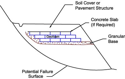
The density of geofoam is 50 to 100 times lower than soils. Acceptable improvement in safety factor can be achieved by soil excavation and replacement with geofoam in the driving block. Such improvement in stability occurs without requiring a change in the final slope geometry. The excavation back slope would be sloped to be self supporting. Free draining material would be placed as transition between the natural soil and the geofoam along the back slope and as leveling course along the base. The final geofoam block configuration balances the amount of geofoam required (cost) with other design and construction factors such as ease and quickness of construction, traffic and environmental impacts, and construction space limitations. Provision of a concrete slab cover may not be necessary. |
|
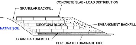
Installing EPS geofoam into an embankment requires that existing soil fill material be removed. Sloped excavations that roughly parallel the shape of the geofoam fill and the existing failure surface facilitate construction. Sloped excavations may not be possible in some cases due to construction right-of-way limitations, requirements related to traffic, poor soil, or a combination of these factors. |
|
|
|
|
|
|
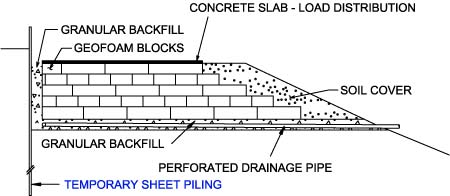
Where inclined excavations are not an option, a temporary steel sheet-pile wall may be installed to permit vertical excavation adjacent to the geofoam fill, as shown below. In both sketches, the concrete slab and pavement are optional. |
|
|
|
|
|
|
|