By Gregory Reuter,
P.E, P.G, Consulting Geotechnical Engineer
and Engineering
Geologist, GME Consultants, Inc., Minneapolis, Minnesota.
Introduction
A segment of County Trunk Highway "A", located within a remote region of Bayfield County
in northern Wisconsin, required continued patching and maintenance of the pavement due to the
presence of a slow-moving, creep landslide. The problem persisted for over 20 years until it
was decided that remedial work be performed in order to stabilize the landslide movement.
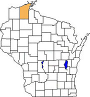
Location of Bayfield County, Wisconsin
Landslide Description
The landslide caused subsidence and cracking within an approximately 45 m wide section of
highway embankment. The highway embankment was originally constructed over a ravine formed
by a nearby creek, with the creek being diverted through a culvert beneath the embankment.
Geologically, the area is overlain by glacio-lacustrine soils deposited during the final
retreat of the Wisconsinan glacial ice sheet, within high water stages of what is presently
Lake Superior. These soils generally consist of very soft, highly plastic clays and silts.
The thickness of these water-lain soils is estimated to be over 50 m at the project site.
The failure occurred within the approximately 14 degree side slope of the embankment fill.
The elevational height between the head of the slide and the toe was about 5 m. Well-defined
tensile and lateral shear cracks within the asphalt pavement of the highway had developed along the head of the
slide, even though the bituminous wear course through this area was frequently patched.
The geotechnical exploration included the measurement of piezometric levels, and the measurement
of deep-seated movement through the installation of an inclinometer within the body of the
landslide. Sufficient creep movement was measured over the few weeks following
installation of this instrumentation to help define the location of the subsurface failure
plane. This allowed for the reconstruction of the slide geometry needed for the
back-calculation of the residual shear strength along the surface of sliding.
Remedial Design
The failure surface was found to occur at a depth of 6.1 m below grade at the location of
the inclinometer casing. At first glance, a simple alternative for stabilization would
seem have been to completely excavate all of the soil within the slide mass and replace
it with compacted granular fill; however, this approach would have meant temporarily closing
the highway, which is a main thorough-fare for the local residents. In addition, the
excavation would have extended below the water table in order to reach the deep sliding
surface, requiring extensive groundwater control and surface water diversion of the creek.
To reduce the driving moment of the slide, it was decided to partly excavate the embankment
fill from within the head of the slide and replace it with lightweight polystyrene geofoam,
as shown in the following figure.
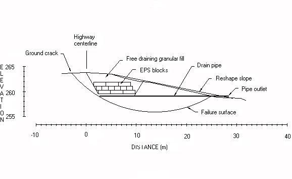
Generalized cross-section showing geofoam placement
Differential Icing
Due to the insulating effects of geofoam, an important consideration when using geofoam
beneath pavements, particularly in northern climates, is the potential development of
differential icing on the pavement surface. This is defined as the formation of ice on the
surface of an insulated pavement when the adjacent, non-insulated pavement is free of ice.
Unlike bridge deck icing, which can be anticipated by motorists, differential icing along a
normal stretch of highway cannot be anticipated, and therefore can pose a serious safety
problem. The intent is not to eliminate icing, but to attempt to time the formation, and
degree of severity, of ice formation to be nearly compatible with icing over non-insulated
areas (Horvath, 1995). Therefore, the top of the geofoam was embedded at a depth of 1.5 m
below final pavement grade, which is consistent with the anticipated frost depth in the
Bayfield County area.
Construction
Buoyancy is also a concern with geofoam. Prior to placing the geofoam blocks, a drainage
blanket and leveling pad were constructed at the base of the excavation, consisting of a
0.3 m thick layer of free-draining sand. Within this drainage layer a 200 mm diameter
slotted plastic pipe was placed parallel to the road
centerline at the back of the excavation. Additional perforated drain lines were installed
extending out perpendicular from the centerline pipe at regular intervals, which
daylighted the final embankment face.
The thickness and location of the geofoam installation were determined through a series of
stability analyses in order to achieve a post-construction factor of safety of 1.5 with
respect to global stability. Based on the results of these analyses, three layers of geofoam
blocks were placed on top of the drainage blanket, with each layer stair-stepped upward and
into the embankment. Each of the layers extended out perpendicular from the road
centerline and were orientated such that each successive layer was placed with the long axis
of the blocks perpendicular to the previous layer. The blocks were shipped to
the site by tractor-trailer truck; however, no special equipment was required for unloading
and placing the blocks since each block was light enough to be handled manually.
Field placement of the geofoam
The backfill surrounding and overlying the block layers consisted of compacted free-draining
sand. To reduce the potential for deterioration by petroleum infiltration from possible
spills or leaks from the highway vehicular traffic, the geofoam was covered with an
impermeable sheeting prior to placing the final fill over the top of the geofoam blocks.
Conclusion
A number of considerations must be reviewed in deciding an appropriate remedial measure for
landslide stabilization. The use of lightweight geofoam provides a viable solution
particularly where the reduction of the landslide driving force is required without
permanently lowering the grade at the head of the slide. The use of lightweight EPS
geofoam on the CTH "A" project allowed for a rapid construction process, which reduced the
amount of over-all excavation required, and minimized the impact of construction on the
continued use of the highway. The work was completed during the summer of 1999, and
the slope has performed satisfactorily since its remediation.
References
Horvath, J.S., Geofoam Geosynthetic, Horvath Engineering P.C., 1995
Negussey, D., "Properties & Applications of Geofoam," Society of the Plastics
Industry, Inc., 1997
Reuter, G.R., and Rutz, J., "A Lightweight Solution for Landslide Stabilization,"
Geotechnical Fabrics Report, Vol. 18, No. 7, September, 2000, p. 42-43
 |
|
|
|
|
|
|
|
|
|
|
|
|
|
|
|
|
|
|
|
|